


Gasket
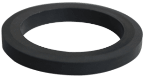
Standard KAMLOK couplers are equipped with Buna-N (NBR) gaskets.
Gasket list
Select and use the right gasket for your fluid and operating conditions.
- * The temperature ranges in which gaskets can be used are provided below. However, this does not guarantee usability under a wide variety of operating conditions (fluids, pressure, number of connections/disconnections, etc.).
- * Do not use gaskets made of fluorine resins (PTFE and FEP). Such gaskets are inelastic and may result in leakage when used with gases. Depending on operating conditions, leakage may occur even within the reference operating temperature range.
-
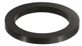
Buna-N (NBR) (standard equipment) Reference operating temperature range:−10 to 100°C
Suitable for use with water, oils, fats, etc.
-
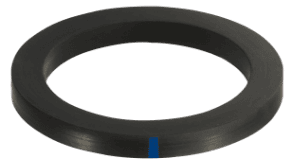
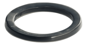
Neoprene (CR) Reference operating temperature range:−30 to 80°C
Excellent weather resistance, heat resistance, and chemical resistance. With blue mark
-
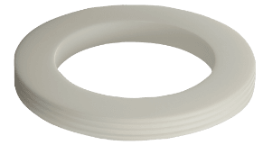
Fluorine resin (PTFE) (solid) *2 Reference operating temperature range:−50 to 100°C
Compliant with Ministry of Health, Labour and Welfare Notification No. 370 regarding the Food Sanitation Act. Excellent chemical resistance, heat resistance, and cold resistance.
-
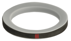
Fluorine resin (PTFE) jacket (with fluororubber) *2 Reference operating temperature range:−0 to 180°C
Excellent heat resistance and chemical resistance. With red mark
-
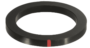
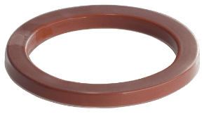
Fluororubber Reference operating temperature range:−0 to 180°C
Excellent heat resistance and chemical resistance. With red mark
-
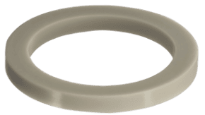
Silicone rubber Reference operating temperature range:−50 to 150°C
Compliant with Ministry of Health, Labour and Welfare Notification No. 370 regarding the Food Sanitation Act. Excellent chemical resistance, heat resistance, and cold resistance.
-
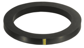
Ethylene-propylene rubber (EPDM) Reference operating temperature range:−10 to 120°C
Excellent heat resistance and chemical resistance. With yellow mark
-
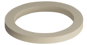
White neoprene (CR) Reference operating temperature range:−10 to 80°C
Excellent weather resistance, heat resistance, and chemical resistance.
-
Super fluororubber *1 Reference operating temperature range:−0 to 180°C
Compliant with Ministry of Health, Labour and Welfare Notification No. 370 regarding the Food Sanitation Act. Excellent heat resistance and chemical resistance. OK to use with steam
-
Silicone rubber fully covered with fluorine resin (FEP) *2 Reference operating temperature range:−50 to 120°C
Excellent chemical resistance and cold resistance.
-
Fluororubber fully covered with fluorine resin (FEP) *2 Reference operating temperature range:−0 to 120°C
Excellent chemical resistance and heat resistance.
- *1 For couplers with a super fluororubber gasket used with saturated steam, the coupler should be used at an operating temperature of no more than 160°C and an operating pressure of no more than 0.6 MPa.
- *2 For couplers with a fluorine resin (PTFE) (solid) gasket, fluorine resin (PTFE) jacket (with fluorine rubber), silicone rubber gasket fully covered with fluorine resin (FEP), or fluororubber gasket fully covered with fluorine resin (FEP), steam cleaning or high-temperature cleaning should be performed with the adapter connected. In addition, when disconnecting the coupler after cleaning, do so after the gasket has reached room temperature. Exposing the gasket to high temperatures without the coupler and adapter connected can cause the gasket to become deformed, resulting in fluid leakage.
Gasket specifications table
| Model | GK-NBR | GK-CR | GK-PTFE | GK-TJ/F | GK-FKM | GK-Q | GK-EPDM | GK-WCR | GK-FKM/S | GK-TZ/Q | GK-TZ/F | |
|---|---|---|---|---|---|---|---|---|---|---|---|---|
| Product appearance | |
|
|
|
|
|
|
|
|
|
|
|
| Material | Buna-N (NBR) | Neoprene (CR) | Fluorine resin (PTFE) (solid) |
Fluorine resin (PTFE) jacket (with fluororubber) |
Fluororubber | Silicone rubber | Ethylene-propylene rubber (EPDM) | White neoprene (CR) | Super fluororubber | Silicone rubber fully covered with fluorine resin (FEP) | Fluororubber fully covered with fluorine resin (FEP) | |
| Size | 1/2”~6” | 1/2”~6” | 1/2”~6” *1 | 1/2”~4” | 1/2”~3” | 1/2”~6” | 1/2”~3” | 1/2”~2 1/2”,4” | 1/2”~2” | 1/2”~4” | 1/2”~4” | |
| Reference operating temperature range: | Upper limit | 100℃ | 80℃ | 100℃ | 180℃ | 180℃ | 150℃ | 120℃ | 80℃ | 180℃ *2 | 120℃ | 120℃ |
| Lower limit | ‐10℃ | ‐30℃ | ‐50℃ | 0℃ | 0℃ | ‐50℃ | ‐10℃ | ‐10℃ | 0℃ | ‐50℃ | 0℃ | |
| Food Sanitation Act compliant | 〇 | 〇 | 〇 | |||||||||
| Usable with steam | 〇 *2 | |||||||||||
- *1 When using a fluorine resin (PTFE) (solid) gasket, select a coupler, adapter, and gasket of the same size.
Example: Combine a coupler 1/2" size, an adapter 1/2" size, and a fluorine resin (PTFE) (solid) gasket 1/2" size for use. - *2 For couplers with a super fluororubber gasket used with saturated steam, the coupler should be used at an operating temperature of no more than 160°C and an operating pressure of no more than 0.6 MPa.
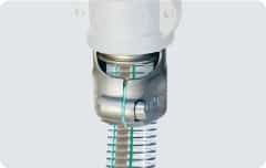
Gasket replacement method
Gasket replacement guidelines
If the tightness of cam arms is reduced when connecting or disconnecting the KAMLOK, the sealing performance of the gasket may deteriorate, resulting in leakage. Replace the gasket with a new one in such cases. TWINLOK gaskets are recommended for safety reasons to prevent deterioration of the sealing property of the gasket when used with steam or at high temperatures, which could cause cam arm disengagement.
Replacement procedure
-
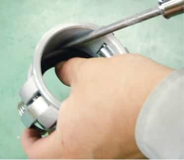
1 Insert a flat-blade screwdriver or similar tool between the main body and the gasket. -
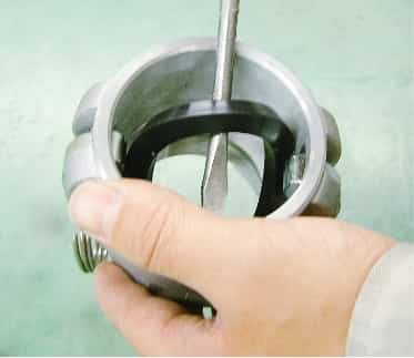
2 Remove the gasket, being careful avoid damaging the gasket seat on the main body. -
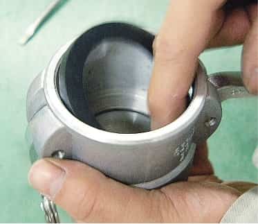
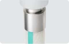
3 Replace the gasket with a new one and push it in manually. -
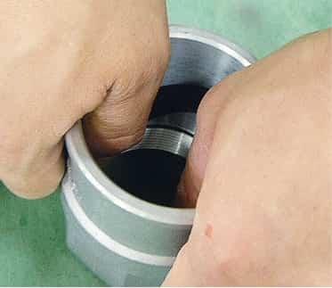
4 Push the gasket in with both hands so that the entire gasket is as level as possible. -
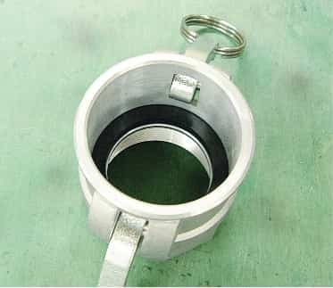
5 Confirm the gasket is properly seated in the groove on the main body to complete replacement.
* When removing the gasket, note that parts of the gasket may break off and remain in the coupling. This may cause problems with foreign substance contaminants or prevent proper installation of the new gasket.
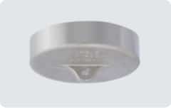
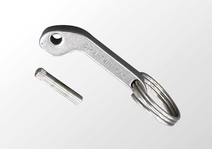
Cam arm & pin
- These are replacement parts for couplers.
- The cam arm, pin, and ring are sold together as a 3-piece set.
- Note that the size of the cam arm varies depending on the size of the product.
- Specify the product material when ordering.
Cam arm replacement procedure
Items to prepare
-
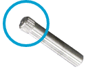
Pin *1
-
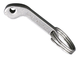
Cam arm (with ring) -
- Tools
- Use commercially available tools

Pin driving tool 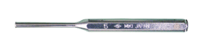
Pin removal tool
*1 Knurled part (Pin knurling is limited to 5 inches.)
Replacement procedure
* Do not replace the cam arms of polypropylene products more than once.
-
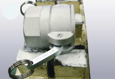
1 Place the main body on the stand with the knurled part on the bottom. -
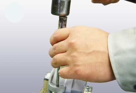
2 Use the pin removal tool to remove the pin from the main body. -
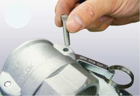
3 Replace the cam arm with a new one, set it in the main body, and insert the pin with the knurled part toward the top. (The knurled part will be on the opposite side of the cam arm being replaced.) -
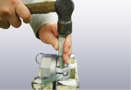
4 Use the pin driving tool to drive the pin into the main body. (The pin should be flush with the surface of the main body.) This completes the replacement procedure.
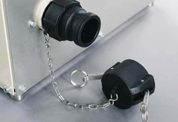
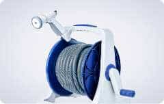
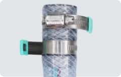
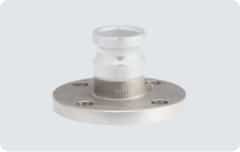
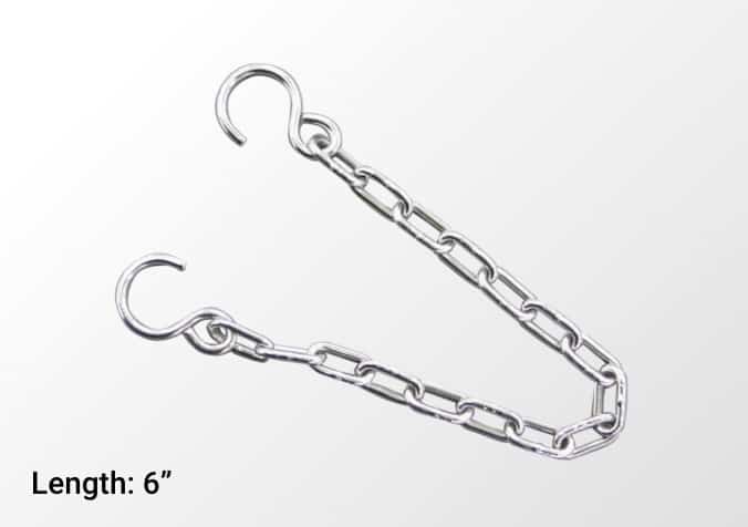
Chain
- This product is used to prevent the dust plug (634-A) or dust cap (634-B) from being lost.
- The material used is SUS 304.
- The two available lengths are 6”(15 cm) and 12”(30 cm).
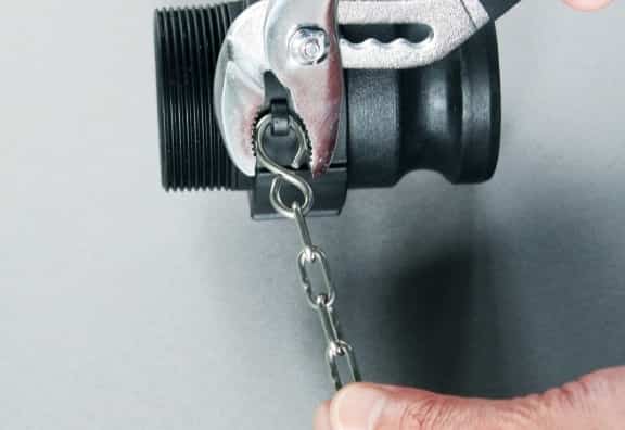
Example of chain use
* Close the end with pliers.