
 GLOBAL














 GLOBAL
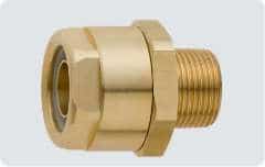
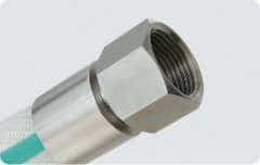
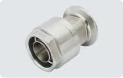
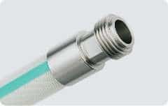
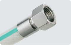
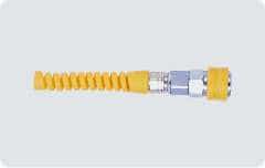
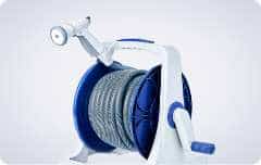
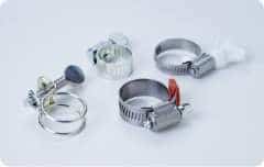
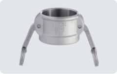
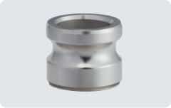
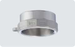
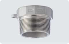
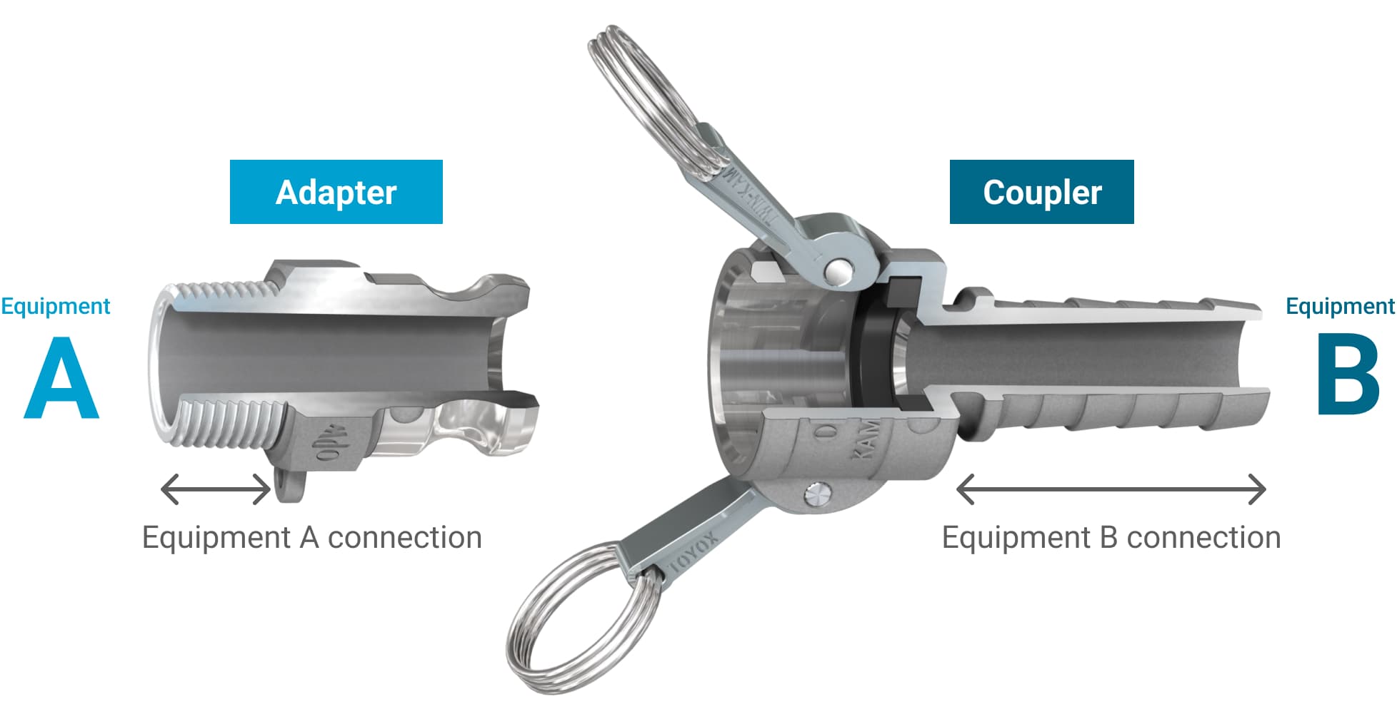
KAMLOK Consists of Four Parts
Select a KAMLOK based on the adapter-to-coupler connection as well as the connections to Equipment A and Equipment B.
How to Select
To select the right KAMLOK, work through the connection type, material, and other requirements in the following order.
-
STEP 01
Select
an adapter -
STEP 02
Select
a coupler -
STEP 03
Select
the size
(nominal diameter) -
STEP 04
Select
the material -
STEP 05
Select
by pressure -
STEP 06
Select
a gasket* The selection may need to be changed depending on the fluid.
step 01
Select an adapter
Select an adapter to match the connection type on Equipment A.
Select the connection type for Equipment A.
Equipment A
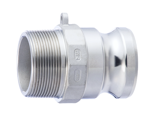
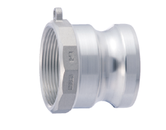
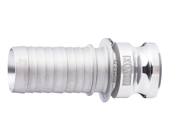
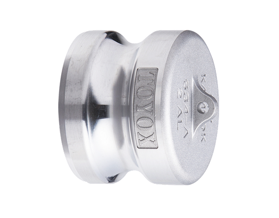
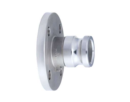
Select the connection type for Equipment A from the options on the left.
step 02
Select a coupler
Select a coupler to match the connection type on Equipment B.
Select the connection type for Equipment B.
Equipment B
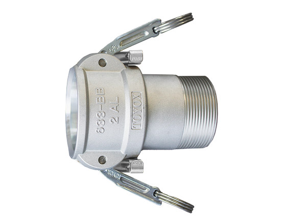
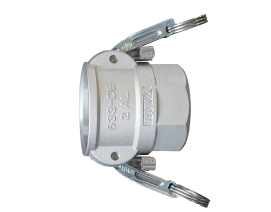
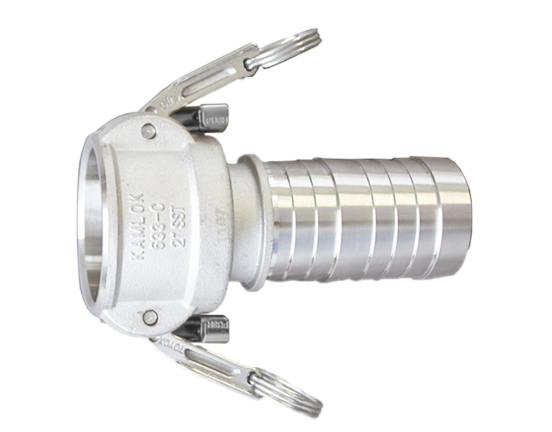
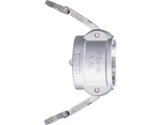
Select the connection type for Equipment B from the options on the right.
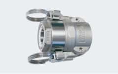
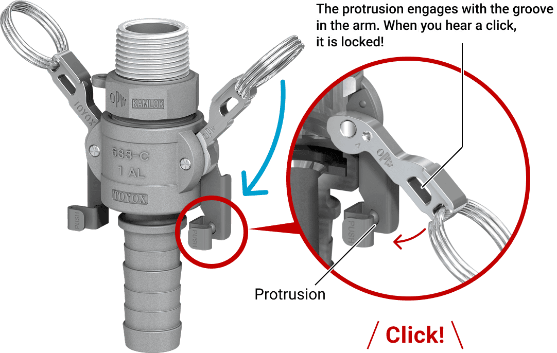
TWINLOK Coupler
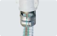
Lower the arms until they click to lock the connection.
Preventing the arms from loosening and the coupling from disconnecting ensures safer, more reliable connection and disconnection.
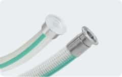
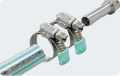
TOYOCONNECTOR Coupler
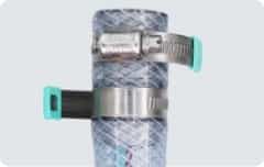
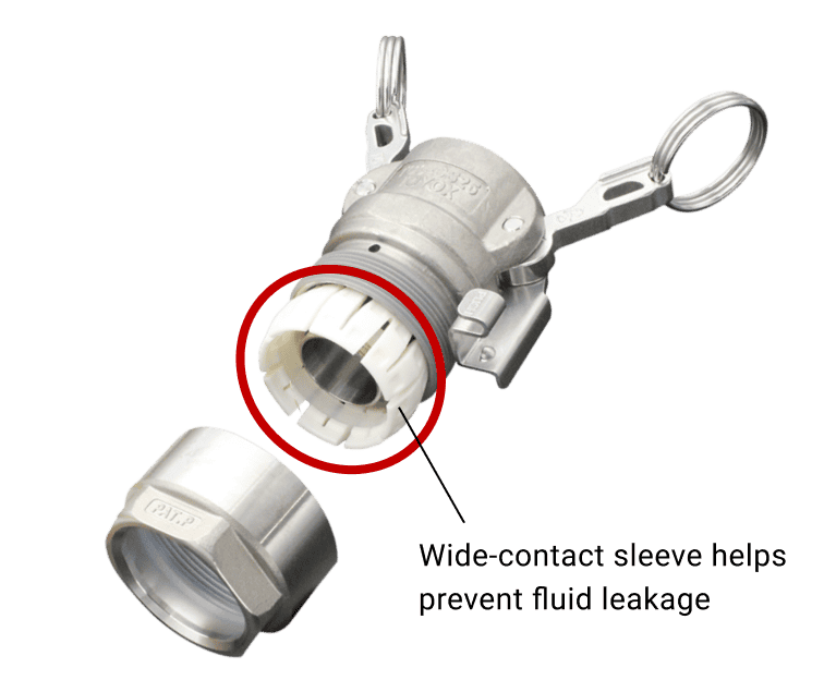
Toward zero fluid leakage and hose disconnection problems.
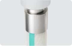
The MS (Multiple-Seal) structure compresses and securely holds the hose over a wide area, helping prevent fluid leakage and hose disconnection. No retightening is required.
step 03
Select the size (nominal diameter)
Check the nominal diameter in the equipment or piping specifications, drawings, markings, or other relevant information.
| in. | 1 2 | 3 4 | 1 | 1 1 4 | 1 1 2 | 2 | 2 1 2 | 3 | 4 | 5 | 6 |
|---|---|---|---|---|---|---|---|---|---|---|---|
| mm | 15 | 20 | 25 | 32 | 40 | 50 | 65 | 80 | 100 | 125 | 150 |
step 04
Select the material
- Aluminum alloy
- Stainless steel
- Resin (PP)
- Bronze
* When the body material is resin (PP), the operating temperature range is 0–60°C. For all other body materials, the operating temperature range is determined by the temperature rating of the gasket used.
step 05
Select by pressure
The values below are reference operating pressure ranges at 23°C when using a Buna-N (NBR) gasket.
(Unit: MPa)
| Material Size | 1/2 | 3/4 | 1 | 1 1/4 | 1 1/2 | 2 | 2 1/2 | 3 | 4 | 5 | 6 |
|---|---|---|---|---|---|---|---|---|---|---|---|
| AL | - 0.1~1.8 | - 0.1~1.1 | - 0.1~0.9 | - 0.1~0.7 | - 0.1~0.5 | ||||||
| SST | - 0.1~1.8 | - 0.1~1.6 | - 0.1~1.4 | - 0.1~1.1 | - 0.1~0.5 | ||||||
| PP(23℃) | ー | - 0.1~0.7 | ー | - 0.1~0.7 | ー | - 0.1~0.4 | ー | ||||
| PP(60℃) | ー | - 0.1~0.25 | ー | - 0.1~0.25 | - 0.1~0.10 | ー | - 0.1~0.05 | ー | |||
| BR | - 0.1~1.8 | - 0.1~1.1 | - 0.1~0.9 | - 0.1~0.7 | ー | ||||||
step 06
Select a gasket
Standard Gasket
Buna-N (NBR)
The standard gasket is the Buna-N (NBR), with an operating temperature range of -10 to 100°C.
* Not compliant with Japan’s Food Sanitation Act.
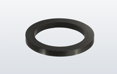
Replacement Gasket List
Select a suitable replacement gasket if the required operating temperature is outside the -10 to 100°C range or if compliance with Japan’s Food Sanitation Act is required.
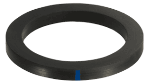
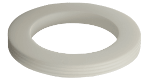
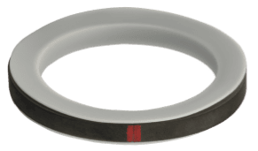
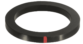
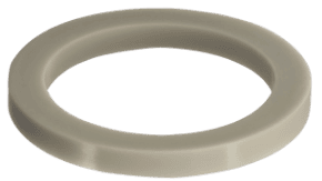
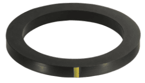
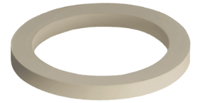
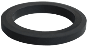
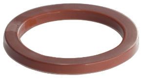
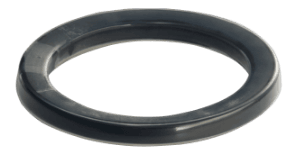
| Model | GK-NBR | GK-CR | GK-PTFE | GK-TJ/F | GK-FKM | GK-Q | GK-EPDM | GK-WCR | GK-FKM/S | GK-TZ/Q | GK-TZ/F | |
|---|---|---|---|---|---|---|---|---|---|---|---|---|
| Product appearance | 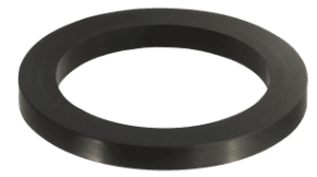 |
 |
 |
 |
 |
 |
 |
 |
 |
 |
 |
|
| Material | Buna-N (NBR) | Neoprene (CR) | Fluorine resin (PTFE) (solid) |
Fluorine resin (PTFE) jacket (with fluororubber) |
Fluororubber | Silicone rubber | Ethylene-propylene rubber (EPDM) | White neoprene (CR) | Super fluororubber | Silicone rubber fully covered with fluorine resin (FEP) | Fluororubber fully covered with fluorine resin (FEP) | |
| Size | 1/2”~6” | 1/2”~6” | 1/2”~6” *1 | 1/2”~4” | 1/2”~3” | 1/2”~6” | 1/2”~3” | 1/2”~2 1/2”,4” | 1/2”~2” | 1/2”~4” | 1/2”~4” | |
| Reference operating temperature range | Upper limit | 100℃ | 80℃ | 100℃ | 180℃ | 180℃ | 150℃ | 120℃ | 80℃ | 180℃ *2 | 120℃ | 120℃ |
| Lower limit | ‐10℃ | ‐30℃ | ‐50℃ | 0℃ | 0℃ | ‐50℃ | ‐10℃ | ‐10℃ | 0℃ | ‐50℃ | 0℃ | |
| Compliance with Food Sanitation Act | 〇 | 〇 | 〇 | |||||||||
| Usable with steam | 〇 *2 | |||||||||||
*1 When using a solid fluorine resin (PTFE) gasket, select a coupler, adapter, and gasket of the same size.
Example: Use a 1/2" solid fluorine resin (PTFE) gasket together with a 1/2" coupler and a 1/2" adapter.
*2 For couplers with a super fluororubber gasket used with saturated steam, the coupler should be used at an operating temperature of no more than 160°C and an operating pressure of no more than 0.6 MPa.

